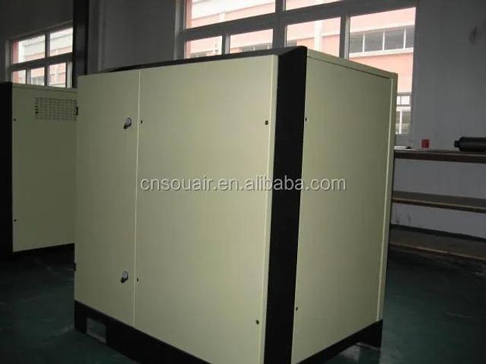
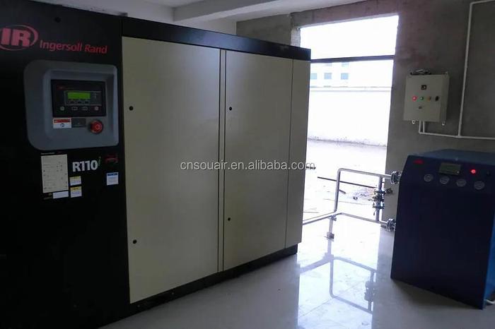
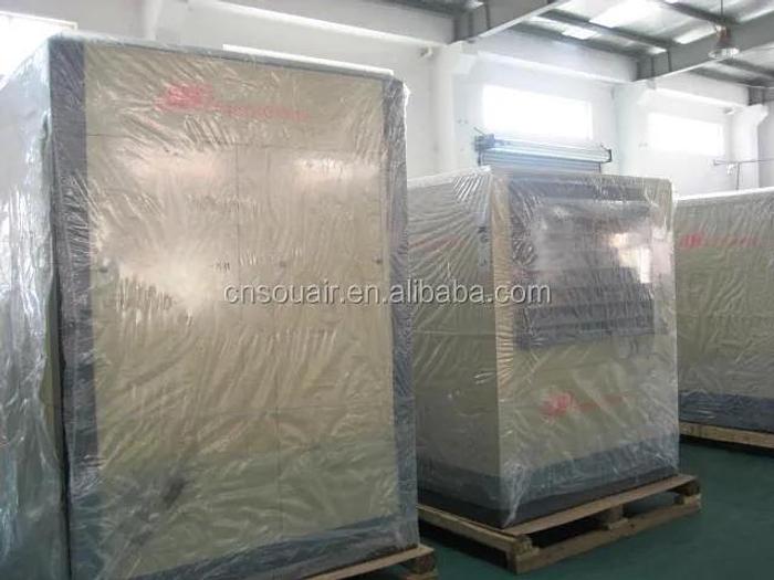
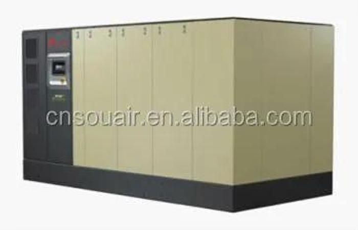
Hot sales 110KW 20.76M3/min 7.5bar Ingersoll-Rand Oil Injected Screw Air Compressor
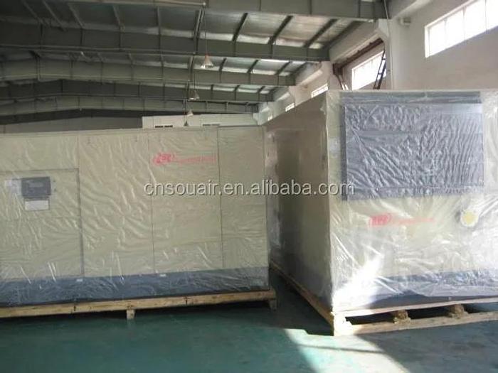
Hot sales 110KW 20.76M3/min 7.5bar Ingersoll-Rand Oil Injected Screw Air Compressor
Description
INGERSOLL RAND R series single stage, contact cooled, rotary screw packaged air compressor.
GENERAL PACKAGE DESCRIPTION
The fully packaged single stage, contact cooled, rotary screw air compressor is designed for total convenience, it is easy to install, simple to operate and will deliver rated compressed air with reliable efficiency. The enclosure is designed to manage the environment of the internal components and the cooling ventilation system, at the same time as significantly reducing the sound level emitted from the machine into the installation environment. The complete package is designed to be located on an adequate flat floor without any special foundations and will operate without imparting significant vibrations to the installation.
INLET AIR FILTER
Inlet air filtration is accomplished by a large 99.9% efficient at 3 micron and above, dry type air cleaner. This is more than suitable for the vast majority of applications: however, where high dust and dirt contamination is present, optional filtration systems are available.
COMPRESSION MODULE
Since the airend is the fundamental component in any rotary screw compressor package, reliability, performance and efficiency are determined for the most part by the design, manufacturing tolerances and assembly of the airend itself. All other elements in the compressor system are essentially support and monitoring devices included to ensure dependable service and performance.
The rotors are manufactured from AISI-1045 steel or EN 10083-2 C45+N steel. The asymmetrical helical profile is developed through a unique two step machining process. The first step in the machining process develops the basic wrap angle profile and is a rough cut. The second and final step is a finish grinding process which ensures a hard, true rotor surface. Rotor shafts are precision ground to tolerances within 0.5mil or 0.0005 of an inch. The rotors are paired prior to assembly into the rotor housing. The rotor housings are made of close grain high quality cast iron. After machining the housing is dimensionally checked to ensure accuracy.
The bearing configuration used is back to back tapered roller bearing. The tapered roller bearing essentially consists of constructing the roller elements, as well as the raceways, so that lines drawn coincident with the working surfaces of the rollers and races will all meet at a common point on the axis of bearing. This allows the bearing to handle all loads, radial, thrust or both. With this bearing configuration, the discharge end of the male and female rotors are each equipped with a pair of tapered roller bearings offset at opposing axes for maximum absorption of thrust and radial loads.
High quality cylindrical roller bearings are used to carry the radial loads on the inlet end of the rotors. All bearings whether thrust or radial, use premium cost vacuum degassed bearings, which provide truer, harder running surfaces for both inner and outer bearing races. To ensure these bearings are always lubricated the airend is equipped with unique “coolant dams” which retain a reservoir of coolant in the bearings, providing lubrication at all times, particularly during start up when immediate lubrication is critical.
MAIN DRIVE MOTOR (Fixed Speed)
General The main drive motor is exactly matched to the requirements of the compressor. Torque and shaft load requirements of the compressor were matched to design criteria that enabled the specified motor to develop peak efficiency and power factor at full load of the compressor package. Standard units are supplied with IP55 four pole motors.
Frame The cast iron frame motor is foot and flange mounted. The frame design is specified to provide maximum strength and rigidity for bearing support, uniform stator/rotor gap and permanent alignment of all mating parts.
Electrical Design Speed, torque and operating characteristics have been designed to match the load of the compressor. Motor efficiency and power factor have been optimized. Standard motors are wound to cover 380, 400, 415, 440, 460 and 575V operation.
Bearings Vacuum degassed bearings provide dependable and reliable service. The motor shaft has the largest possible standard diameter. This means that larger bearings are fitted. These oversized bearings average applied life is approximately five times greater than a standard bearing life. Both bearings are grease lubricated with bearing housings having inlet and relief fittings to simplify the lubrication procedures.
Insulation The Ingersoll Rand dedicated motor has a major benefit in that the maximum temperature rise the motor actually experiences is much lower than the temperature rise permitted by the design of the motor. The motor has class F insulation as standard, which means it is rated at a continuous duty for a temperature rise up to 109°C (228°F). However no motor is ever applied for a temperature rise over 89°C (192°F) in a 46°C (115°F) ambient. This is significant, since the motor life expectancy is doubled with every 10° reduction in temperature rise. The extra conservatism Ingersoll Rand build into the motor means more reliability, increased life, and a much more forgiving motor under adverse conditions. Temperature rise is at the applied load and not the nominal power. All windings and leads are copper with triple coats of insulating varnish to add extra margins of protection to the driver.
MAIN DRIVE MOTOR (Nirvana)
The compressor drive is a Hybrid Permanent Magnet ® (HPM) motor and utilizes an inverter to control its starting, frequency and speed. The HPM motor optimizes torque, efficiency and power factor through the following features:
a)Unlimited number of starts/stops per hour and precise variable speed control to accurately match air demand changes.
b)Premium 95% efficiency.
c)Independent coil modules that accurately respond to a wide range of inverter induced frequencies.
d)1.25 service factor and increased air gap that allows cool operating temperatures at an ambient rating of 46ºC (115ºF).
e)Direct attachment of the HPM motor rotor to the primary rotor shaft which eliminates the friction of motor shaft bearings and the need for energy consuming couplings, belts, or gears.
The HPM stator attaches directly to the airend adapter flange and completes the motor/airend assembly.
In summary, the installation of this compact HPM motor directly to the airend increases efficiency and reliability by eliminating energy robbing components and by significantly reducing the number of serviceable parts.
INTEGRAL DRIVE ASSEMBLY (Fixed Speed)
In order to maximize the inherent efficiency advantage of the Ingersoll Rand motor and airend it was necessary to develop a means of efficiently and reliably transmitting power from the driver to the compressor. The Ingersoll Rand integral gear drive system was engineered to operate without losses or slip and without mechanical complexity of alignment compensating couplings. The reliable and rugged design has been refined and proven over more than a quarter century of use.
Conservatively chosen speed optimizing gears are mounted on the shafts of the airend and motor. The flanged motor is doweled for permanent alignment to the airend. The use of smooth running helical gears cause the airends to always rotate at the selected speed which provides consistent capacity and efficiency. The gear housing is completely sealed against atmospheric contaminants to ensure lifetime trouble-free power transmission. A self-centering Teflon impregnated motor shaft seal provides a positive system against leakage to the motor winding.
VIBRATION MOUNTS
The airend/motor module is mounted to the sub-base on anti-vibration pads. This makes these compressors silent and smooth running.
LUBRICATION SYSTEM
Coolant Filtration The full capacity coolant filter is a 5 micron replaceable element. Filter condition is monitored by the Intellisys controller which provides a warning when filter differential reaches 1.8 bar (25 psi). The system contains an internal pressure relief that bypasses at 2.5 bar (36 psi) in the event that the change warning is not acknowledged.
Coolant/Lubricant Temperature Control The thermostatic control valve with four ports, (1) for the coolant from the pressurized receiver/separator, (2) for the coolant from the valve to the cooler, (3) for the coolant from the cooler, and (4) for the coolant to the coolant filter, is mounted in the piping system. The temperature sensitive element controls the quantity of coolant from each source, cooled and un-cooled as necessary to provide the proper injection temperature, assuring fast warm-up and avoiding potentially harmful condensation.
Coolant Injection The coolant is injected through a single large port on the female rotor inlet side. This ensures the best possible pre-sealing of the rotor, plus an optimum mix of coolant with inlet air. Coolant flow is maintained by the differential pressure between the separator tank and the airend inlet.
COOLANT/AIR SEPARATION
After compression and discharge from the airend, the air heavily laden with coolant travels to the receiver/separator. Entering through a tangential inlet, the air coolant mixture is directed in a circular motion around the inside of the tank. The vortex or the circular motion separates a major portion of the coolant from the air through centrifugal force. The air is then directed through baffles, which further reduces the coolant content. The vortex action and impingement on baffles results in a pre-cleaning of the compressed air prior to entering the separator element.
Separator element is two-stage molded fiberglass structurally reinforced coalescing separator. There is a scavenge line which picks up coolant which has coalesced on the inside of the separator element and feeds it back to the airend inlet. The carryover after the separator element is less than 3 ppm. Due to the conservative sizing of the separator element there is a minimal 3 psi (0.2 bar) pressure drop. This reduces the required power to move the air through the compressor system.
The separator tank is mounted vertically in the compressor with the airend discharge entering near the bottom. The separator vessel is protected by pressure relief safety valve mounted on the side of the tank. There is a coolant drain valve at the bottom of the tank which is piped out to the sub-base and a coolant filler point which is located so that it is not possible to overfill the compressor with coolant. There is also a coolant sight level glass on the side of the tank. The air discharge from the separator is regulated by a minimum pressure check valve which ensures that, when the unit is unloaded, sufficient pressure is maintained in the tank to propel the coolant through the system.
Pressure reducing blow down valves on the separator tank allow the pressure in the separator tank to be reduced when the machine is unloaded, when this valve opens and the internal pressure falls to approximately 20 psig (1.4 barg) which fully reduces the unloaded power requirement.
Ingersoll Rand compressors are supplied with a factory fill of Ultra Coolant. Ingersoll Rand Ultra Coolant is a highly advanced, 100% synthetic lubricant with a long service life, of two years or 8000 hours (whichever occurs first).
COOLERS
R series compressors are available as air-cooled or water-cooled units as standard. Both types of compressor have two heat exchangers, an after-cooler to cool the discharge air and a coolant cooler.
In standard air cooled units the discharge air is cooled to within 5ºC (9ºF) of the ambient temperature, basis 46ºC (115ºF) and 40% RH. In air-cooled units cooling air which is drawn into the enclosure passes over the main motor and airend and is then forced out through the series flow aftercooler and oil cooler. The coolers are of an aluminum finned tube construction and are designed to operate continuously, fully loaded in ambient air up to 46ºC (115°F) without exceeding the normal design coolant injection temperature.
Air-cooled Nirvana models utilize a "COOLANT CONDITIONER" system to ensure that proper lubricant temperature is maintained. The system is a combination of an inverter controlled cooling blower motor, and coolant system thermostatic control valve. The Intellisys microprocessor receives data from the cooling system, calculates a system pressure dewpoint, then directs the blower motor inverter to work in conjunction with the thermostatic control valve. This sophisticated system is required to:
a)Ensure that damaging moisture does not accumulate in the coolant system
b)Support effective after-cooling within the entire performance range of the compressor
c)Provide significant sound reduction at partial loading
d)Furnish energy savings associated with the inverter controlled blower motor
Water-cooled machines have an aftercooler CTD of 15ºF (8.3ºC) and can be adjusted depending on the available cooling water temperature and flow. Cooling is achieved with parallel water flow into the two coolers and is designed for cooling water inlet temperatures up to 115ºF (46ºC). Cooling water passes through alternating plates and the compressed air through the adjacent plates. The heat exchangers are constructed of ANSI 316 stainless steel plates with copper braze. The heat exchanger passages may be cleaned with the proper chemical cleaning agents
FAN MOTORS
In air-cooled machines, the TEFC high efficiency motor and the low noise, high pressure, centrifugal blower are mounted behind the coolers. This forces a cooling air flow through the cooler prior to exiting the enclosure. A residual pressure of 0.25 inch (6 mm) H2O is available for ducting losses. In water-cooled machines, supply pressure sustains the cooling flow and a much smaller motor and fan are used to circulate air around the enclosure.
COMPRESSOR/ CAPACITY CONTROLS (Fixed Speed)
As standard, R90-R110 units are provided with on line/off line control. This control strategy allows the compressor to operate at 2 points on the capacity curve. The first is 100% full-flow and the second is 0 flow. On line/off line control is a power savings mode of operation where the unloaded operation provides for immediate compressor system blow-down to minimize power requirements. The compressor will automatically reload to 100% capacity when the system pressure falls to a predetermined pressure.
Ingersoll Rand R90-R110 units are fitted with automatic stop/start as standard. This allows the compressor to run unloaded for a predetermined time, and if there is no demand within that period, the unit shuts down to standby, consuming zero energy and will automatically restart and load if the pressure falls to a preset level.
The time at which the compressor is operating most inefficiently is when the compressor is running unloaded. The Intellisys controller will monitor the compressor’s operating cycle and reduce the off load running time to a minimum.
Upper range modulation control is an option on these compressors. Refer to the option section for details.
COMPRESSOR/ CAPACITY CONTROLS (Nirvana)
The compressor is controlled via the Intellisys controller. This microprocessor allows for turndown range to 35-61% at a system efficiency of 92% or greater. Below the minimum turndown, the control methodology turns the compressor unit off, taking advantage of the HPM’s unique ability to have unlimited starts and stops. Because Nirvana does not blowdown, and can start under a load, Nirvana will turn itself off at minimum speed and remain off until system pressure decays below operator set target pressure. The control methodology operates under a constant specific power throughout the entire pressure and turndown range.
STARTER (Fixed Speed)
The standard compressor has an integrally mounted IP65 (NEMA 4) starter box, with a hinged door panel. It contains starter contactors, control transformer and all the components of the control circuit. The wye-delta starter is used to reduce the current inrush on starting. The control relays operates at 110V AC and the control circuit is protected by miniature circuit breakers or fuses. All electrical equipment is designed to conform to the applicable local electrical codes. An optional electronic soft starter is available.
INVERTER (Nirvana)
As standard with the package, the compressor has an integral inverter to match to the HPM motor. The inverter is standard type with a minimum efficiency of 96%. Integral to the drive module is the control voltage circuit to provide control power for all control circuits.
INTELLISYS MICROPROCESSOR CONTROLLER
The compressor is monitored, controlled and protected by the intuitive Intellisys microprocessor controller. The Intellisys continuously monitors the status of the compressor and takes immediate action if an abnormal operating condition occurs, and displays the relevant message on the display.
The compressor emergency stop button will stop the compressor independently of the Intellisys unit. The controller offers advanced protection for the compressor in the event of voltage failure or instability.
Operation of the controls is simple and user friendly.
Optional Equipment
HIGH DUST FILTER (Fixed Speed Only)
This is a heavy duty filter, enclosed in a plastic shroud, for use in dirty, dusty environments. The filter has two stages of separation; a centrifugal primary stage is employed to mechanically separate larger dust particles which are ejected, followed by a high capacity dry type filter element. Together these give a high filtration capacity with an efficiency of 99.9% at 3 microns and above.
COOLANT
Ingersoll Rand R series machines are supplied with a factory fill of Ultra Coolant as standard. Optionally they may be supplied from the factory with H-1F food grade coolant with X-TEND life enhancing filter. Food Grade coolant requirements must be specified on the order. Otherwise the factory will supply Ultra Coolant.
COMPRESSOR/ CAPACITY CONTROLS (Fixed Speed)
Modulating inlet control automatically matches air capacity to demand. This control method reduces the delivered air volume by causing a pressure reduction in the intake port. When modulation is fitted and selected, partial closure of the intake valve in direct relation to fall and rise of pressure will cause variable air volume delivery.
Modulation is available on R models as an option. Modulation control is particularly useful where air demands vary between 60 & 100% (which is most common situation) and where there is some reasonable amount of system storage capacity.
Modulation avoids the frequent cycling which is sometimes associated with on-line/off-line control when insufficient system capacity is available, in which case modulation reduces the thrust loads on bearings and cycling of solenoid valves.
LOW AMBIENT FREEZE PROTECTION (Fixed Speed Only)
Starting a compressor with viscous coolant, condensation within the electrical components or frozen condensate drainage systems can all result in damage. To protect against such event the Intellisys controller will warn if freezing conditions occur at start-up, and if heaters are fitted will execute a warm-up cycle prior to loading. For units to be installed in conditions with temperatures down to -10ºC (14ºF) (-23°C, -10°F for North America), Ingersoll Rand offer a combination of heating elements in the starter panel, trace heating and motor heaters or fan assisted space heaters to prevent moisture or freezing of condensate when the unit is shut down. The heaters can be wired directly to a suitable customers’ supply voltage or through the starter so they can switch on when the units shut down. Through a VFD on the blower, the Intellisys controller maintains proper compressor temperatures even in the cold environment. NOTE: Outdoor Modification is a separate option and can be ordered in conjunction with freeze protection.
SEQUENCE CONTROL
The Intellisys control fitted to the R90-110 compressor is suitable for use with Ingersoll Rand approved energy management controllers. In addition, the controller on the fixed speed unit can automatically sequence up to four compressors fitted with the same controller via the RS485 serial communication interface, sharing running hours, operating on a common pressure range and changing running order in accordance with a pre-programmed schedule.
When controlling an air system with an Ingersoll Rand Air System Controller, which sequencers multiple compressors and accessories, connect directly to the compressors via the RS485 serial communication interface
PORO, AUDIBLE RESTART WARNING KIT
For the “real time clock” timed operation function which is available within the Intellisys controller, or for customers who anticipate interruptions in their incoming power supplied to their compressors, but need to maintain their supply of compressed air, the Power Outage Restart Option allows the compressor to restart automatically within an adjustable time period after incoming power is restored following power interruption.
The option is a field fit modification kit, which consists of an audible warning device and full fitting instructions. The siren, which sounds when power is restored to the compressor, warning people in the vicinity that the unit is about to start. This is mounted into the instrument panel.
OUTDOOR INSTALLATION RAIN INGRESS PROTECTION (Fixed Speed Only)
Intended for operation between temperatures of 35ºF (2ºC) through 115ºF (46ºC) in installations which may be exposed to rain ingress this option will ensure that sensitive electrical areas are ingress protected and any water penetration into general machine is channeled out of the enclosure appropriately.
ELECTRONIC SOFT STARTER (Fixed Speed Only)
The optional soft start facilitates reducing starting current to the lowest value achievable, compatible with positive starting of the drive motor. This system is offered to overcome issues where local equipment is sensitive to, or expected to be effected by disturbances in power supplies caused by relatively high starting currents and transient spikes caused by traditional contactor switching motor starters.
REGULATORY SPECIFICATIONS
Dependent on local code requirements, the following standards are complied with:
Electrical Components: NFPA70/79, IEC60204, and GB5226-1 compliant
ISO1217 Annex C; 1996 for performance testing and acceptance criteria.
ISO2151:2004 noise test code, and noise measurement standard ISO9614-2:1996 and defined as sound pressure level at the workstation, +3 dB(A)
Pressure Vessels (regional variations):
ASME Pressure Vessel Code; Section VIII, Division 1, “Unfired Pressure Vessels”
87/404/EC Simple Pressure Vessel directive or 97/23/EC for non simple vessels
GB 150 (1998) Steel Pressure Vessels
Specifications
| Manufacturer | Ingersoll-rand |
| Condition | New |
| Type | Screw |
| Configuration | Stationary |
| Power source | AC POWER |
| Lubrication style | Lubricated |
| Mute | Yes |
| Place of origin | Shanghai China |
| Model number | R110I-A7.5 |
| Voltage | 400 V/50Hz/3Ph |
| Dimension(l*w*h) | 2703/1466/2032 |
| Weight | 2550Kg |
| Warranty | 12months |
| After-sales service provided | Overseas service center available |
| Certification | ISO |
| Ingersoll-rand compressor | screw air compressor |
| Color | Yellow |
| Power | Electric |
| Bearing | SKF |
| Cooling method | Air Cooling |
| Working pressure | 102 Psi |
| Motor power | 110KW Compressor |

